

Post Tension Anchor Company Essentials for Safer Concrete Structures
2026-11-16
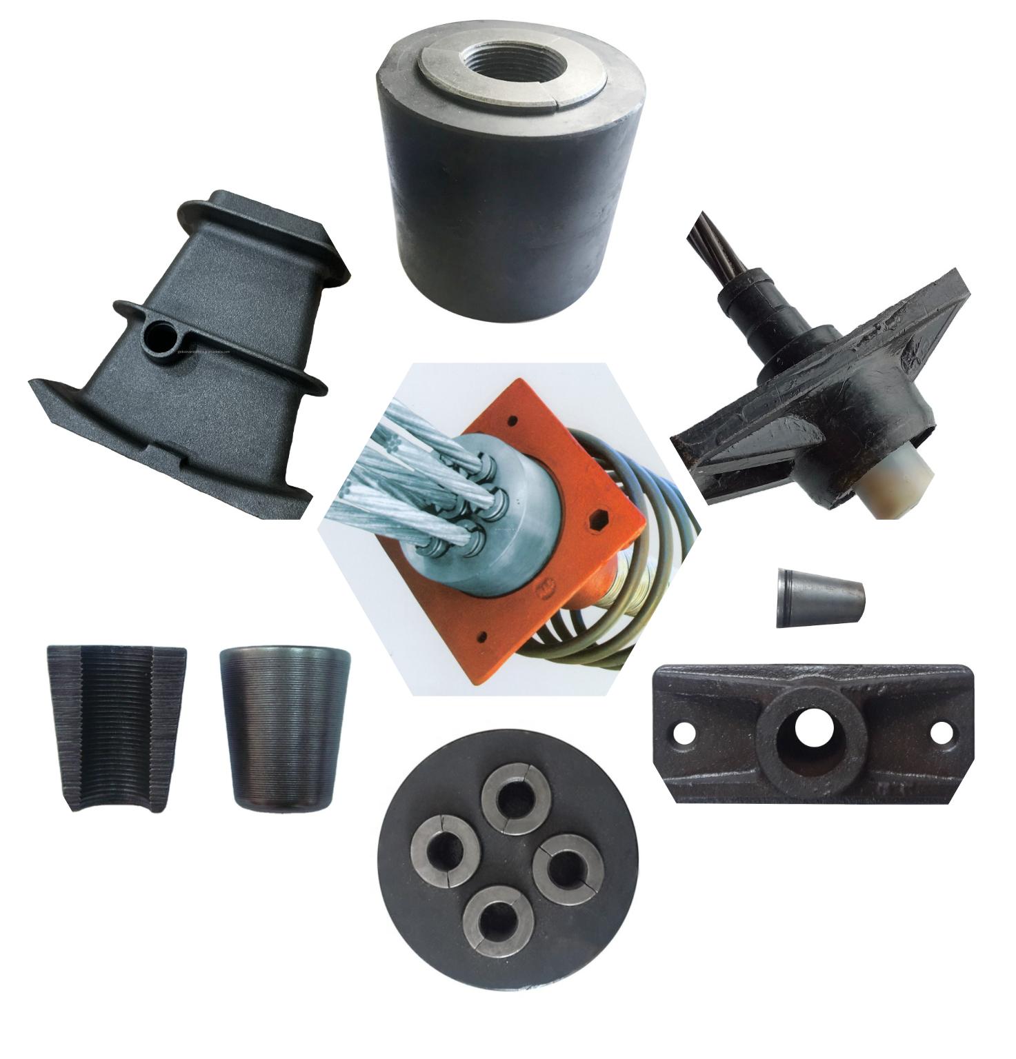
Concrete may be the backbone of modern construction, but without the right anchorage, even the strongest slab can fail under tension. Post-tension anchors are the quiet workhorses that keep structures safe, transferring immense loads without a whisper of complaint. Yet not every anchor is built to the same standard—subtle differences in design, materials, or manufacturing can mean the difference between decades of durability and a sudden, costly failure. That’s where Supreme Machinery steps in, redefining what it means to anchor with confidence. In this post, we’re pulling back the curtain on the essentials every engineer, contractor, and project owner should demand from a post-tension anchor company—before the first pour ever happens.
The Overlooked Role of Wedge Geometry in Anchor Grip
Most anchor failures aren't material deficiencies but the result of a wedge whose taper angle doesn't match load direction. A shallow angle can produce enough expansion force to split brittle substrate; steeper angles reduce splitting but demand more friction to prevent slip. Engineers often default to standard angles without checking how the contact patch evolves under torque.
Surface finish and edge chamfer on the wedge matter just as much. A polished wedge slides too easily at initial set, while a rough machined surface creates micro-interlocking that delays relaxation. The transition from cone to cylindrical body, if too abrupt, concentrates stress and can shear the anchor at modest loads.
In field conditions, wedge geometry also controls how tolerances stack. Oversized holes or out-of-round drilling change the effective bearing area, and a wedge with a longer tapered section tolerates misalignment better than a short steep one. This is why some anchors hold in perfect test blocks but creep in weathered concrete.
Corrosion Inhibition Tactics for Aggressive Environments
In aggressive environments—think chloride-laden coastal air, acidic industrial runoff, or high-temperature process streams—standard corrosion inhibitors often fail because they are designed for mild conditions. A more reliable tactic is to combine anodic and cathodic inhibitors into a synergistic blend, but the ratio must be tuned to the specific electrolyte chemistry. For instance, a molybdate–phosphate pair works well in near-neutral brines, yet adding a small amount of zinc salt can dramatically improve film persistence on steel exposed to intermittent wet–dry cycles. The key is not just selecting the right compounds, but also understanding how they compete for surface sites when multiple aggressive species are present.
Another undervalued approach is to manipulate the local pH and oxygen availability at the metal interface rather than relying solely on adsorption. In highly acidic environments, volatile corrosion inhibitors such as amine carboxylates can migrate through void spaces and neutralize acidic condensates before they reach the substrate. Meanwhile, for buried or submerged structures, injecting a slow-release inhibitor gel into the surrounding soil or water creates a protective reservoir that continuously replenishes the passive film. This tactic works especially well when conventional coatings have already been breached by abrasion or stress cracking.
Finally, real-time adjustment of inhibitor dosage based on electrochemical noise or linear polarization resistance data can extend service life far beyond what static dosing achieves. Rather than maintaining a constant concentration, a feedback loop lowers inhibitor feed during periods of low corrosivity and ramps it up when chloride spikes or temperature excursions occur. This not only reduces chemical consumption but also avoids the pitfall of over-inhibition, which in some systems can accelerate localized attack by promoting uneven film growth. The most robust tactics treat inhibition as a dynamic, site-specific process rather than a one-size-fits-all recipe.
Tensioning Sequences That Reduce Structural Stress
Bolted joints rarely fail because a single fastener was pulled too tight. The real culprit is almost always uneven load distribution—one side of the flange ends up carrying far more than its share, while the other side barely feels a thing. That imbalance is what eventually leads to leaks, cracks, or outright flange failure. A well-planned tensioning sequence doesn't just tighten bolts; it choreographs the way clamping force spreads across the entire assembly, keeping stress gradients shallow and predictable.
The classic star or cross pattern gets most of the attention, but the choice of sequence should also account for joint geometry and gasket behavior. For circular flanges, you want to pull opposing bolts in small, staged increments—never more than a third of the target torque in one pass. This lets the gasket seat evenly and avoids pinching one side while the other is still loose. On rectangular or irregular patterns, start from the center and work outward in alternating directions, mimicking how a wave of compression naturally wants to travel through the material.
Another often-overlooked detail is the final pass. Many procedures call for a last full sweep at the specified torque, but that sweep should follow the exact same sequence as the initial passes, not simply go clockwise around the rim. Doing a clockwise final check can unknowingly introduce a subtle bias, since each previously tightened bolt interacts with its neighbor. If you want to reduce residual stress, close the loop by returning to your starting point and verifying at least two bolts on opposite sides have not relaxed below spec.
Field Verification Tools Beyond Standard Checklists
Moving past paper checklists often means adopting mobile apps that let field teams capture photos, GPS tags, and voice notes directly on site. These tools don't just record a pass or fail—they build a timeline of evidence that can be revisited if a dispute or audit comes up later. A technician might snap a picture of a loose fitting, mark the exact location on a floor plan, and flag it for immediate review, all without switching devices.
Some teams rely on sensor-based verification for conditions that are hard to judge by eye. Thermal cameras, ultrasonic thickness gauges, and vibration meters can feed readings straight into a shared dashboard. Instead of asking someone to rate a weld as 'acceptable,' the tool measures temperature differentials or material loss in real time. This shift reduces the influence of fatigue or personal bias, which is especially valuable on long shifts or remote sites where a second opinion isn't available.
Beyond data capture, newer platforms layer in workflow triggers and smart defaults. If a pressure reading falls outside a set range, the system can automatically assign a follow-up task or lock the next step until the issue is acknowledged. That kind of built-in logic turns verification from a static record into an active guardrail, helping crews catch problems before they cascade into costly rework or safety incidents.
Material Traceability From Mill to Installation
Every heat produced at the mill carries a unique identifier that stays with the material through rolling, cutting, and coating. This heat number links the physical plate or section back to its exact chemical composition and mechanical test results, so any discrepancy found later can be traced to the source without guesswork. On site, the same identifier appears on delivery notes, stickers, and stamped edges, making it possible to reconcile what was ordered with what actually arrived.
Once materials reach the fabrication shop or jobsite, traceability depends on disciplined handling rather than just paperwork. Cut-offs are re-marked before being moved, and welders log heat numbers against joint locations in their daily records. This creates a continuous chain from mill certificate to installed position, which is especially important when a project requires EN 10204 3.1 or similar certified documentation.
At installation, the final as-built package ties every traceable item to a specific elevation, gridline, or equipment tag. If a question arises years later—whether about a batch of bolts, a steel beam, or a length of pipe—the project team can pull the original mill data without reopening the whole supply chain. That level of visibility reduces rework and gives owners confidence that the materials in place match the approved submittals.
Designing Redundancy Into Anchor Placement
Placing a single anchor on a page assumes every visitor will follow the same path, but real browsing habits are far messier. Users might land mid-page from a shared link, scroll past a primary jump point, or have their viewport cut off a sticky button depending on screen size. By designing redundancy into anchor placement, you give people multiple chances to reach the same destination without forcing them to hunt for the one link that should have been obvious. This might mean repeating a call-to-action anchor near the top and bottom of a long article, or tucking a secondary anchor into a sidebar that stays visible during scroll.
The trick is to avoid turning redundancy into clutter. Rather than copying the same anchor text three times in a row, look for natural pauses in the content where a reader might reasonably want to jump elsewhere. A mid-page anchor after a key section, a footer anchor for those who finished reading, and a lightweight icon anchor in the margin can all point to the same form or product page without feeling repetitive. Each instance should blend into its immediate context, using slightly different wording or styling so the page doesn't read like a broken record.
Testing is where most redundant anchor schemes either prove their worth or fall apart. Watch session recordings to see where users actually try to click when they decide to leave a section. If a secondary anchor receives almost no interaction, it may be too hidden or simply unnecessary for that page's flow. Conversely, a repeated anchor that gets used heavily from an unexpected area might signal a change in reading order that deserves a more prominent placement. Adjust the duplicate anchors based on actual behavior rather than assumptions, and remember that redundancy works best when it quietly supports a clear task, not when it shouts for attention.
FAQ
It locks the high-strength steel strands in place after they've been tensioned, transferring the compressive force into the concrete. Without a reliable anchor, that tension can't be maintained and the whole system loses its purpose.
They allow slabs and beams to carry heavier loads with less cracking and deflection. By keeping the steel tendons under controlled stress, anchors help the concrete stay in compression where it's strongest, reducing sudden failures.
Look beyond the product catalog. Check their testing documentation, failure rates, and whether they offer technical support during installation. A good company will also have anchors designed to match specific duct and strand sizes rather than forcing generic fitments.
Yes, anchors made from high-grade ductile iron or forged steel with corrosion-resistant coatings like epoxy or zinc perform better in aggressive environments. The choice depends on exposure, but skimping on coating is a common cause of premature deterioration.
Misaligned wedges, inadequate seating of the anchor head, and failing to clean the strand before locking are common. Any of these can lead to uneven stress distribution and eventual slippage under load.
It directly affects it. Reputable manufacturers test every batch for hardness, dimensional accuracy, and load capacity. Inconsistent QC means some anchors may pass visual inspection yet fail in service, creating hidden risks.
Direct load testing of buried anchors isn't practical, but you can monitor tendon elongation during stressing, inspect exposed anchor heads for cracks or corrosion, and use non-destructive methods like radiography on critical elements.
Conclusion
The quiet failures in post-tensioned concrete rarely begin with the steel strand snapping mid-span. More often, trouble starts at the anchor, where wedge geometry and grip mechanics decide whether the system holds its design force for five years or fifty. A post tension anchor company that treats wedge angle, tooth profile, and seat concentricity as mere catalogue specs invites slow slippage and unexpected relaxation. The best suppliers scrutinize wedge hardness gradients and surface treatments, because a wedge that seats too shallow can chew through strand wires, while one that bites too deep creates stress risers. This is not about meeting a minimum breaking load; it is about maintaining grip under live load oscillations and thermal cycling without fretting or micro-slip.
Equally decisive are the less glamorous layers: corrosion inhibition tactics tuned to aggressive environments, tensioning sequences that distribute stress rather than piling it onto end anchors, and field verification tools that go beyond ticking standard checklists. A reliable post tension anchor company pushes for material traceability from mill heat number to final installation torque, so any unexpected tendon behavior can be traced to its metallurgical root. It also designs redundancy into anchor placement — not by over-sizing every component, but by ensuring that a single localised anchorage issue cannot trigger progressive unzipping of the entire tendon path. When wedge grip, corrosion defence, sequencing logic, verification depth, and traceability are woven together, safer concrete structures stop being a hope and become a repeatable outcome.
Contact Us
Contact Person: Paul
Email: [email protected]
Tel/WhatsApp: 8615067447509
Website: https://www.spironcasting.com