
Metal Shredder Fabrication Techniques for Building Durable Industrial Shredders
2026-09-09
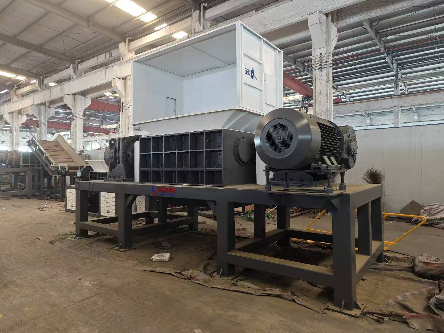
Ask any maintenance manager what kills a metal shredder, and you’ll rarely hear about the motor first. It’s the fabricated core—rotor, housing, liners—that takes the daily beating. In this post, we dig into the metal fabrication techniques that separate a shredder built to survive from one that merely looks heavy. That’s also why Shengzhong Shredder applies stress-relieved welds, precision rotor balancing, and abrasion-resistant liners across its industrial lineup.
Alloy and Heat Treatment Choices That Keep Shredder Knives Cutting Longer
The real lifespan of a shredder knife rarely comes down to a single material spec. It is the way alloy composition interacts with the dominant wear mechanism in your specific feed stream. For example, higher vanadium grades like M4 or CPM-10V excel at resisting abrasive wear from fiberglass, minerals, or heavily contaminated plastics, but they can be brittle on impact if the scrap contains a lot of tramp metal. Conversely, a tough shock-resistant grade such as S7 or A8 will shrug off occasional hard objects, yet it may need more frequent resharpening when the main challenge is fine grit. Matching the carbide type and volume fraction to the failure mode you actually see on used blades usually gives a bigger improvement than simply chasing a higher Rockwell number.
Heat treatment is where most off-the-shelf knives fall short. A blade can have the right chemistry and still lose its edge quickly if the austenitizing temperature, quench speed, or tempering cycle is optimized for a generic tooling application rather than shredding. Multiple tempering steps are often necessary to convert retained austenite in high-alloy steels; without that, the edge can deform or micro-chip under load. Deep cryogenic treatment between quench and temper also helps refine the martensitic structure and relieve residual stress, which translates to less edge rolling and more predictable wear. Even small differences in soak time at the final temper can shift the hardness by only a point or two but change impact toughness by a wide margin.
Some operators get the best value from hybrid approaches: a tough core alloy with a hardened case, or a hard-facing overlay on the cutting edge only. Nitriding, boronizing, or laser cladding with a wear-resistant alloy can be applied selectively so the body of the knife remains ductile while the working surface stays sharp longer. If your knives tend to crack near mounting holes or show deep gouges from occasional unshreddables, the solution may not be a harder blade overall but a better distribution of hardness between the edge and the carrier. Getting this balance right often extends the interval between regrinds more than buying a premium alloy without adjusting the heat treatment.
Weld Sequencing to Stop Frame Cracking Before It Starts
Most frame cracks don't appear in the weld itself—they show up a few inches away, in the heat-affected zone, where the base metal has been pulled, stretched, and locked into a brittle state. The sequence of your welds controls exactly where that residual stress lands. If you lay a long continuous bead along one side of a chassis rail and then immediately weld the opposite side, the first side cools and contracts while the second side is still molten. That contraction pulls the rail toward the first weld, creating a slight bow and a sharp stress riser at the end of the weld. Later, under normal road vibration or a hard bump, that riser becomes the starting point for a crack.
A better approach is to break each joint into shorter segments and alternate sides as you go. Instead of running a full six-inch weld on the driver side, weld two inches there, then move to the passenger side and weld two inches at the same relative position, then come back. This lets each small segment cool and shrink independently without building a long unidirectional pull. The stress distributes more evenly across the frame, and the peak tension at any single point drops low enough that normal service loads stay well under the threshold for crack initiation.
On boxed frames or crossmember joints, add a back-step sequence. Start each weld at the point farthest from the joint's center and move outward, rather than starting at the edge and welding inward. This pulls the edges outward slightly and leaves the center in mild compression, which is exactly the opposite of what you get from a single-pass inward weld. For critical areas like spring hangers or steering box mounts, consider tacking the part in four places, checking for square, then making the final welds in a balanced alternating pattern with no more than one inch of bead per pass. Let the part cool to the touch between sides. It adds a few minutes to the job, but it eliminates the hidden stress pattern that causes most frame cracks long before they become visible.
Rotor Balancing with Precision Machining Rather Than Guesswork
Old-school rotor balancing leaned heavily on trial weights, chalk marks, and a technician’s feel for where metal should come off. Precision machining changes that equation. By pulling vibration data from a balancing machine and turning it into exact toolpaths, a machinist can remove the predicted amount of material at the predicted angular position—no iterative guesswork. The result is a rotor that comes off the mill already closer to its final balance state.
This approach works because the machining center becomes part of the measurement loop. Laser scanning or touch probing maps the rotor’s actual geometry, while the balancer reports the heavy spot and the required correction mass. CAM software then blends those inputs into a smooth cut that blends with the rotor’s surface, often within a few microns. Instead of adding washers or drilling random holes, the process treats imbalance as a machining feature—one that can be located, measured, and eliminated.
When the correction is made by a controlled cut rather than a manual hack, benefits stack up. Bearings see less cyclic loading, vibration drops across the speed range, and the rotor typically needs no secondary balancing pass. Shops that adopt this method often stop stocking balance-weight kits entirely, because the stock removal itself restores symmetry. That’s the practical difference between curing a symptom and removing the root cause.
Hardfacing High-Wear Zones Without Distorting the Base Metal
Hardfacing high-wear zones often comes down to managing heat. When you pour weld metal onto a thin or highly restrained base, the expansion and contraction cycle can pull the part out of shape. A simple trick is to balance the deposit: weld a short bead on one side, then flip the part and run a similar bead on the opposite face before either side cools completely. This opposing shrinkage works like a pre-stress that cancels out much of the distortion, especially on long edges or flat plates.
Another approach is to drop the heat input per pass but increase the number of passes. Using a smaller diameter wire or rod, lowering amperage, and keeping a fast travel speed all help. You sacrifice a bit of deposition rate, but the base metal never reaches the critical temperature where it wants to curl or bow. Peening each bead while it is still warm also helps—light hammer blows stretch the weld metal, forcing it to yield rather than pull the base out of position.
If the part has a thick section or an existing machined surface that cannot tolerate any movement, consider preheating the whole component before welding. A uniform 200–300°F soak reduces the temperature gradient between the weld pool and the surrounding metal, so the cooling contraction is more even. Clamp the workpiece to a heavy steel table or use strongbacks on the backside, but do not over-restrain—allow the weld to flex slightly as it cools, otherwise you risk cracking instead of distortion.
Fabricating Housings with Controlled Forming and Stress Relief
Housings that come off a press still carry the memory of every bend and draw. Without careful management, that stored energy shows up later as warpage or split corners. The approach starts with the forming stage itself: tooling is adjusted in real time to compensate for springback, and lubricant films are mapped across the blank instead of applied uniformly. These small corrections prevent the part from fighting its own geometry before it ever reaches stress relief.
Once the shape is stable enough to handle, the residual stress is drawn down in stages rather than with a single oven cycle. For aluminum housings, a low-temperature soak at 180–220 °C for two to four hours relaxes the worst of the forming stresses without sacrificing temper. Thicker steel housings sometimes respond better to vibratory stress relief, where a controlled frequency sweep coaxes the lattice into a lower-energy arrangement. Either way, the sequence is tied to the specific alloy and wall thickness, not pulled from a generic chart.
Verification closes the loop. A sample batch is cut along the critical radii and checked for dimensional shift over 48 hours; if the flanges move less than the tolerance band, the forming and stress relief parameters are locked. This keeps the housing from creeping after machining or assembly, which is where uncontrolled stress usually makes itself known.
Designing Modular Wear Components for Practical Rebuilds
Modular wear components flip the script on traditional rebuilds. Instead of waiting for a whole assembly to reach end-of-life, you replace only the surfaces that actually take the beating. That might mean swapping out a set of bolt-on liners, a cross-braced wear plate, or a hardened edge section while the main frame stays in place. The real payoff comes in the pit or on the production floor—less downtime, smaller spare parts inventory, and rebuilds that match the actual wear pattern rather than a generic one-size-fits-all schedule.
Getting the design right starts with mapping contact zones. Look at where material rubs, slides, or impacts, then split those areas into distinct modules with a clear interface. A good modular system lets a worn section come off without fighting seized bolts or hidden brackets. Use tapered fits, keyed alignment features, and standardized fastener sizes so crews can finish a swap with basic tools. Adding witness marks or built-in wear indicators helps too—operators spot a module nearing its limit before it damages the base structure.
Material choice matters just as much as geometry. Pair a tough, ductile base module with a harder, more brittle replaceable face—think AR plate liners on a mild steel frame, or cast chromium carbide segments bolted to a fabricated shell. Leave room for a little give: slight clearance between modules prevents stress cracks at the joints while still protecting the structure underneath. Field tests on conveyor skirting and excavator buckets show this approach can cut rebuild time by half and extend intervals between major overhauls by two to three times.
FAQ
Tool steels like D2 or A2 are common, but for extreme impact, modified H13 or S7 alloys hold up better. Many fabricators harden working edges to 55-60 HRC while keeping the core below 45 HRC to absorb shock. Carbide-tipped or solid tungsten carbide blades work for finer shredding, though they cost more and require careful mounting to avoid fracture.
Proper heat treatment creates a hard, wear-resistant surface over a ductile core. Shafts are typically normalized after forging, then induction hardened only at bearing seats and rotor mounting points. Cutting discs often get vacuum austenitizing, oil quenching, and double tempering around 200-300°C. Deep cryogenic treatment after quenching can convert retained austenite, adding a few extra points of wear resistance without brittleness.
An unbalanced rotor creates vibration that destroys bearings, cracks welds, and wastes energy. Even a few grams of imbalance at several hundred RPM produces huge centrifugal forces. Fabricators use dynamic balancing machines to measure the exact correction point. Weight is usually added by welding counterweights or removed by drilling shallow pockets in non-critical areas. Final balance should meet ISO 1940 G2.5 or better.
Thick plate welding demands preheat—usually 150-250°C depending on carbon equivalent—plus low-hydrogen electrodes or solid wire with 75% argon/25% CO2. Interpass temperature must stay above the minimum and below about 300°C to prevent martensite formation and hydrogen pickup. Full penetration joints with U or double-V bevels are standard. Post-weld heat treatment, like stress relieving at 550-600°C, is often applied to large frame sections before final machining.
Casting is better for complex shapes with internal cavities, such as large anvils or grate bars, because it avoids excessive machining time and material waste. Cast steel with manganese or chrome-moly additions gives good work hardening under impact. Machining from forged billet is preferred when tight tolerances or higher tensile strength are needed—for example, hammer pins or high-speed knife holders. Forged hammers generally outlast cast hammers in high-impact applications.
Hardfacing deposits a wear-resistant layer directly onto high-wear zones. Chromium carbide overlay plate is often applied to liners, chutes, and rotor faces; it typically contains 30-40% chromium carbide in a softer steel matrix, with a hardness of 55-65 HRC. Plasma transferred arc welding or laser cladding can apply precise hardfacing on blade edges without excessive dilution. A 3-6mm thick overlay can double or triple service life in abrasive metal shredding.
The key is minimizing downtime. Split housings allow rotor removal without dismantling the entire machine. Bolt-on wear liners and anvils can be replaced with hand tools instead of cutting and rewelding. Cartridge-type bearing units slide off the shaft as one piece. Quick-change blade or hammer systems use taper locks or hydraulic nuts so individual elements can be swapped in minutes. Clearly marked lifting points and accessible inspection ports also speed up routine maintenance.
Conclusion
The durability of an industrial shredder starts long before assembly. Knife alloys chosen for toughness and wear resistance, paired with carefully tuned heat treatments, keep cutting edges sharp under punishing loads. Rather than using a generic tool steel, shops often specify grades that balance hardness with enough ductility to resist chipping. On the frame side, weld sequencing is not just a production detail; it determines whether residual stresses will concentrate at joints and cause cracks after months of vibration. By staggering welds, controlling interpass temperature, and sometimes back-stepping, fabricators can let the structure relax into a lower-stress state. This prevents the kind of hidden fatigue that shows up only after the machine has been in service.
A shredder rotor that is balanced by precision machining rather than trial weights spins true at high rpm, reducing bearing wear and vibration across the whole drive train. Hardfacing high-wear zones adds a sacrificial layer of abrasion-resistant alloy, but it must be applied with controlled heat input so the base metal doesn't warp or lose its properties. Housings benefit from controlled forming followed by stress relief, which keeps dimensions stable and seals tight. Equally important, designing wear parts as modular inserts or bolted segments means a rebuild is a planned maintenance event, not a full teardown. Operators can swap out worn sections and return to full capacity faster, which matters more than initial cost.
Contact Us
Contact Person: Leon
Email: [email protected]
Tel/WhatsApp: 8615385558866
Website: https://www.shred-waste.com