

KYN28-12 Medium Voltage Switchgear ODM Solutions for Dependable Power Distribution
2026-11-16
When power distribution cannot afford a single moment of hesitation, the switchgear behind the scenes has to be more than just reliable—it has to be engineered for the way your facility actually runs. That is where KYN28-12 medium voltage switchgear steps in, and where MOLDVOLT turns a standard cabinet into a tailored ODM solution. Instead of forcing your project into off-the-shelf compromises, this approach starts with your load profile, operating environment, and maintenance reality, then builds backward from there. The result is a power distribution backbone that feels less like purchased equipment and more like a deliberate extension of your own engineering team. In the sections ahead, we will unpack what makes the KYN28-12 platform so adaptable, why ODM thinking changes the reliability equation, and how MOLDVOLT helps you avoid the hidden costs of generic switchgear.
What KYN28-12 Actually Changes on Site
Once the switchgear leaves the factory, the differences show up in how much alignment work the site crew has to do. KYN28-12 cabinets arrive as separate, self-contained units, so the old practice of welding long base channels before positioning panels is mostly gone. Instead, teams spend more time on leveling each cubicle and then pulling the busbar compartment covers to connect the main run. The busbar bolts are accessed from the front, which shortens the shutdown window when a section has to be extended or repaired.
The biggest operational change happens at the earthing switch and the interlock chain. Because the truck and the earthing switch are tied together mechanically, the sequence on site becomes stricter than older mixed installations. A fitter cannot roll the breaker from test to service without first closing the earthing switch, and the cable room door also follows that same logic. That removes at least one workaround crews used to rely on, but it also means commissioning takes a little longer until everyone stops fighting the sequence.
What often gets noticed later is the difference in cable termination space. The rear cable compartment is roomier than many retrofit panels, so stress cones and CT connections are easier to dress without forcing the cable into a tight bend. At the same time, the panel depth increases the footprint, so an existing room with shallow trenches may need civil adjustments before the line-up sits properly.
Where Custom ODM Requests Fit Into the Standard Frame
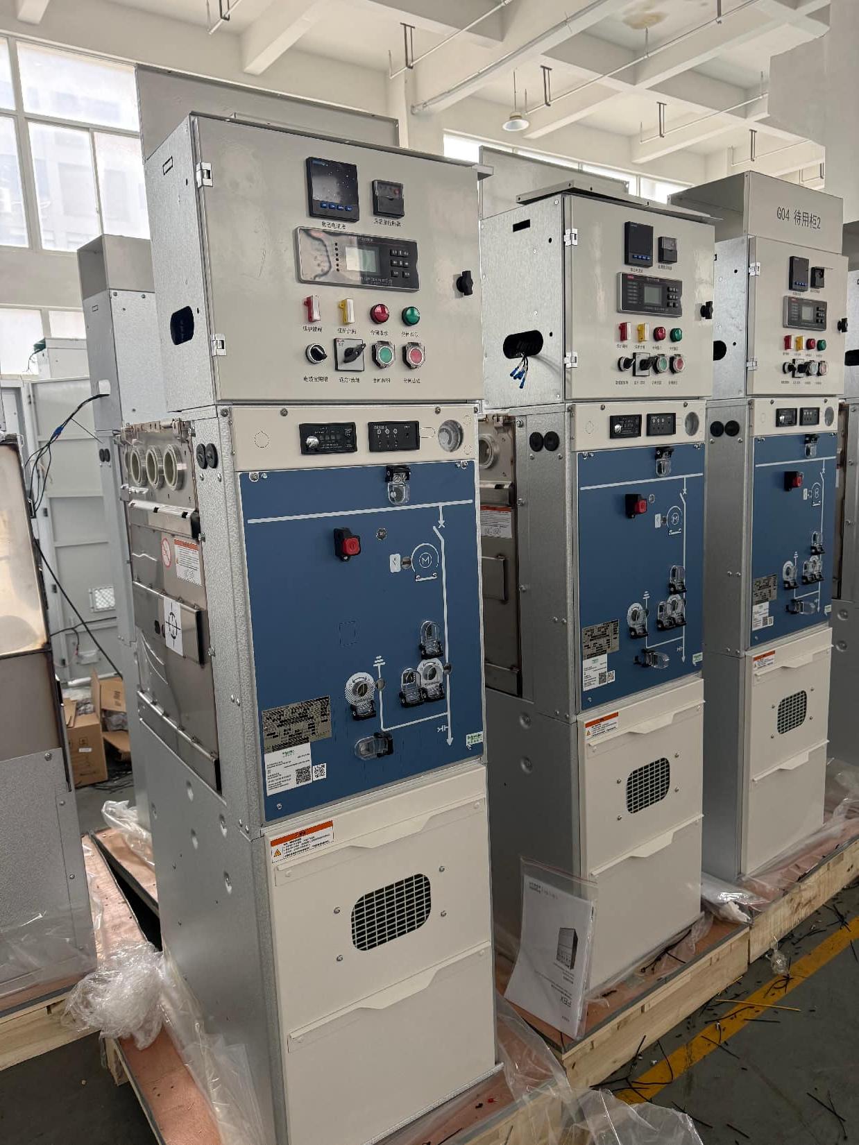
Most custom ODM requests do not need a separate development track. They usually begin as variations of an existing chassis, board layout, or enclosure, and the real task is identifying which elements can shift without disrupting the established manufacturing flow.
The standard frame acts as a boundary rather than a rigid template. Requests that stay inside it, such as different I/O arrangements, branding, voltage adjustments, or firmware defaults, tend to move quickly because the supply chain and assembly steps are already proven. When a request pushes past that boundary, the conversation changes from configuration to feasibility, and timelines are recalculated around tooling, certification, or component sourcing.
Using the standard frame as a shared reference also makes discussions more precise. Instead of asking whether something is possible in general, teams can point to exactly which part of the standard build needs to change, which constraints still hold, and where cost and schedule actually begin to move.
Internal Layout Choices That Make Maintenance Less Painful
The first thing anyone notices when opening the case is that parts you actually need to reach are not buried under a dozen unrelated cables. Wear items like filters and drive caddies sit right behind a single latch panel, so a routine swap does not turn into a teardown. That sounds obvious, but plenty of machines still hide the most serviced parts behind the least accessible corners.
Internally, the cabling paths are shaped rather than stuffed. Bundles run along fixed channels with enough slack to pivot a board without disconnecting half the harness. Color-coded headers and printed labels on the board itself cut down on guesswork when you are holding a flashlight in one hand. Even the screws are a deliberate choice: one common size instead of three nearly identical lengths.
The layout also leaves a clear hand path between the power supply, fan assembly, and main board. That extra inch of empty space feels wasteful on a spec sheet, but it means a failed fan can be replaced without removing the motherboard. If a repair requires more than a few minutes, it is usually a sign the internal order was not designed for the person doing the repair.
Protection Logic Before It Becomes a Fault Event
Most protection schemes only react after a threshold has already been crossed. The more useful approach runs the logic earlier, watching how quickly a measurement is moving rather than waiting for an absolute limit. A temperature that climbs eight degrees in four minutes may still be within the normal band, but that slope tells a different story. By comparing the rate of change against a stored baseline, the control system can open a bypass valve, reduce load, or flag the loop for inspection before the reading ever reaches the shutdown point.
Timing also matters more than the raw value. Two sensors may individually look acceptable even when their relationship has started to drift, and that drift is often the first real signal of a developing problem. Protection logic built around those relationships can catch a blocked filter, a worn coupling, or a failing sensor before any single alarm would fire. The goal is not to replace hard interlocks but to give them fewer reasons to act.
Well-designed pre-fault logic also respects the difference between noise and trend. A single spike should not trigger an unnecessary response, just as a slow but steady shift should not be ignored. Short confirmation windows, simple hysteresis, and lightweight state tracking turn raw data into a reliable heads-up. When the final protective relay does operate, it should feel less like a surprise and more like the last line in a sequence that was already understood.
Factory Discipline You Can Hear in a Clean Close
The clean close doesn’t announce itself with a whistle. It comes through in smaller, sharper sounds: the snap of a clipboard shut, the tick of cooling metal, a trolley’s wheels crossing the last joint in the floor. In this part of the shift, discipline stops being a set of rules and becomes something you can track by ear.
There is a rhythm to the way tools are wiped down and returned, not hurried but timed. Boots move between stations without overlapping. A cabinet door closes with a soft clap, then another, following the same order as yesterday. It’s easy to mistake the room for quiet, but listen longer and you notice the low hum of a line idling, the deliberate pause before someone steps away from a bench. That pause is the sound of a standard being met.
By the time the floor is cleared and the lights dim in stages, the space has been put back into a kind of audible order. The clean close leaves no grand finale, only the faint rustle of cover sheets, a last socket settling into its tray, and the click of a lock as the shift ends. That click is discipline at its plainest: not spoken, not posted on a wall, just heard.
Keeping the Panel Honest Under Real Load
Most ratings look tidy on a spec sheet, but the real test starts when a board is asked to carry sustained current through undersized busbars, ageing breakers, and terminals that have been re-torqued more times than anyone cares to admit. Monitoring a panel under genuine electrical load means watching how heat moves across connections, listening for the faint buzz of a loose lug, and measuring voltage drop while compressors, heaters, and motors cycle together. That is where optimistic numbers quietly fall apart.
The honest approach is to load the panel until it works the way it would on a difficult day, not a lab afternoon. Record temperatures at the neutral bar, compare breaker body heat across phases, and check whether the main lugs stay within a reasonable rise after several hours. A panel that holds steady when the load is uneven, repetitive, and occasionally spiky tells you more than any controlled bench figure. Keep the test messy enough, and the hardware either proves itself or shows exactly where it needs attention.
FAQ
The metal-clad structure and fundamental interlocking logic remain standard, but customers can influence busbar current ratings, internal arc classification, breaker brand, protective relay types, terminal layouts and panel finish. Small-batch customisation is usually handled without redoing type tests from scratch.
The design is typically aligned with IEC 62271-200 and equivalent national standards for metal-enclosed switchgear. Routine tests cover power-frequency withstand, lightning impulse, temperature rise, mechanical operation and partial discharge before dispatch.
It shows up in utility substations, industrial plants, data centers, hospitals and infrastructure projects where a 12 kV distribution point needs to stay compact and serviceable. The withdrawable breaker arrangement makes it suitable for sites that cannot afford long shutdowns.
The KYN28-12 uses a five-way interlock scheme that ties the breaker position, earthing switch, cable compartment door and closing circuit together. You cannot rack the breaker in or out with the door open, and you cannot close the earthing switch while the breaker is in service position.
Maintenance and fault recovery become faster because the vacuum circuit breaker can be racked out and replaced or inspected without de-energizing the entire busbar section. That isolation gap also provides a visible break for safe work.
Yes. The ODM process supports a range of microprocessor-based relays, communication protocols and auxiliary contacts. Control schematics are reviewed against the customer's single-line diagram before production, which reduces site-side rework.
A standard package includes routine test reports, wiring diagrams, component certificates and maintenance instructions. Some projects also ask for factory acceptance test records with customer witnesses or third-party inspection.
The enclosure can be specified with IP4X or higher protection, optional anti-condensation heaters and different paint systems for humid or coastal environments. Internal compartment separation keeps high-voltage parts isolated from cable and low-voltage areas.
Conclusion
A medium-voltage panel can look correct on paper and still create avoidable work on site. The KYN28-12 changes that by keeping the standard frame intact while ODM requirements—busbar ratings, CT layouts, interlock logic—are resolved before installation rather than discovered during it. Cable entry positions, breaker access, and low-voltage compartments are arranged in a way that does not force maintenance crews to fight the equipment. Protection is not left as a generic default. Trip curves, time grading, and zone coordination are set against the actual network conditions so the relay responds early enough to prevent a minor event from becoming a fault.
The build quality is equally telling. Door alignment, bolt torque, wiring dress, and the sound of a clean close are not cosmetic details; they show whether the panel will stay stable under thermal and dynamic loading. ODM customization stays within that discipline, altering copper sizing, auxiliary contacts, or metering channels without weakening the proven structure. That balance is what makes the KYN28-12 dependable in service—it adapts to a site without becoming a one-off experiment, and it keeps maintenance straightforward because the choices made in the factory actually match the loads the switchgear will carry.
Contact Us
Contact Person: Hellen
Email: [email protected]
Tel/WhatsApp: 86-13634205622
Website: https://www.voltcabinet.com