

KYN28-12 Medium Voltage Switchgear Company: Key Factors for Reliable Power Distribution
2026-10-31
In the world of medium voltage distribution, the KYN28-12 switchgear stands as a workhorse—but not all manufacturers build it equal. Behind every reliable power network lies a series of deliberate engineering choices, from busbar design to arc fault containment. This post unpacks what separates a dependable KYN28-12 supplier from the rest, and why MOLDVOLT keeps surfacing in conversations about uptime and safety. If your facility depends on uninterrupted power, the factors below deserve more than a passing glance.
Panel Geometry Choices That Keep Internal Arc Pressure From Becoming a Hazard
Internal arc faults don't just release heat—they create a near-instantaneous pressure spike that can turn a flat panel into a drum head. Panel geometry is often the difference between a controlled venting event and a ruptured enclosure. Deep cabinets, curved or ribbed side sheets, and folded edges all raise stiffness locally, preventing the broad, flat expanses that balloon outward under load. That stiffness forces the blast toward the intended pressure-relief path instead of letting it find the weakest seam or latch.
Avoiding long uninterrupted flat spans is one of the simplest upgrades. A shallow corrugation or a double bend along the sidewall interrupts surface deflection and increases the panel's natural frequency, so it doesn't respond as violently to the impulse. On the door, a slight dome or an offset relative to internal busbars can keep the front cover from becoming a projectile. Multi-point latching around all four edges and a recessed door overlap create a labyrinth that bleeds off pressure before hot gases reach the operator line.
In arc-resistant testing, cabinets with these geometric features consistently show lower peak overpressure at the operator position, even when wall thickness stays the same. The goal isn't just stronger steel—it's shaping the enclosure so that pressure is managed, not contained until failure. Small changes in bend placement, door recess, and latch spacing often outperform a uniform increase in material gauge because they direct the blast instead of simply resisting it.
Busbar Contact Pressure: The Silent Variable Behind Thermal Hotspots
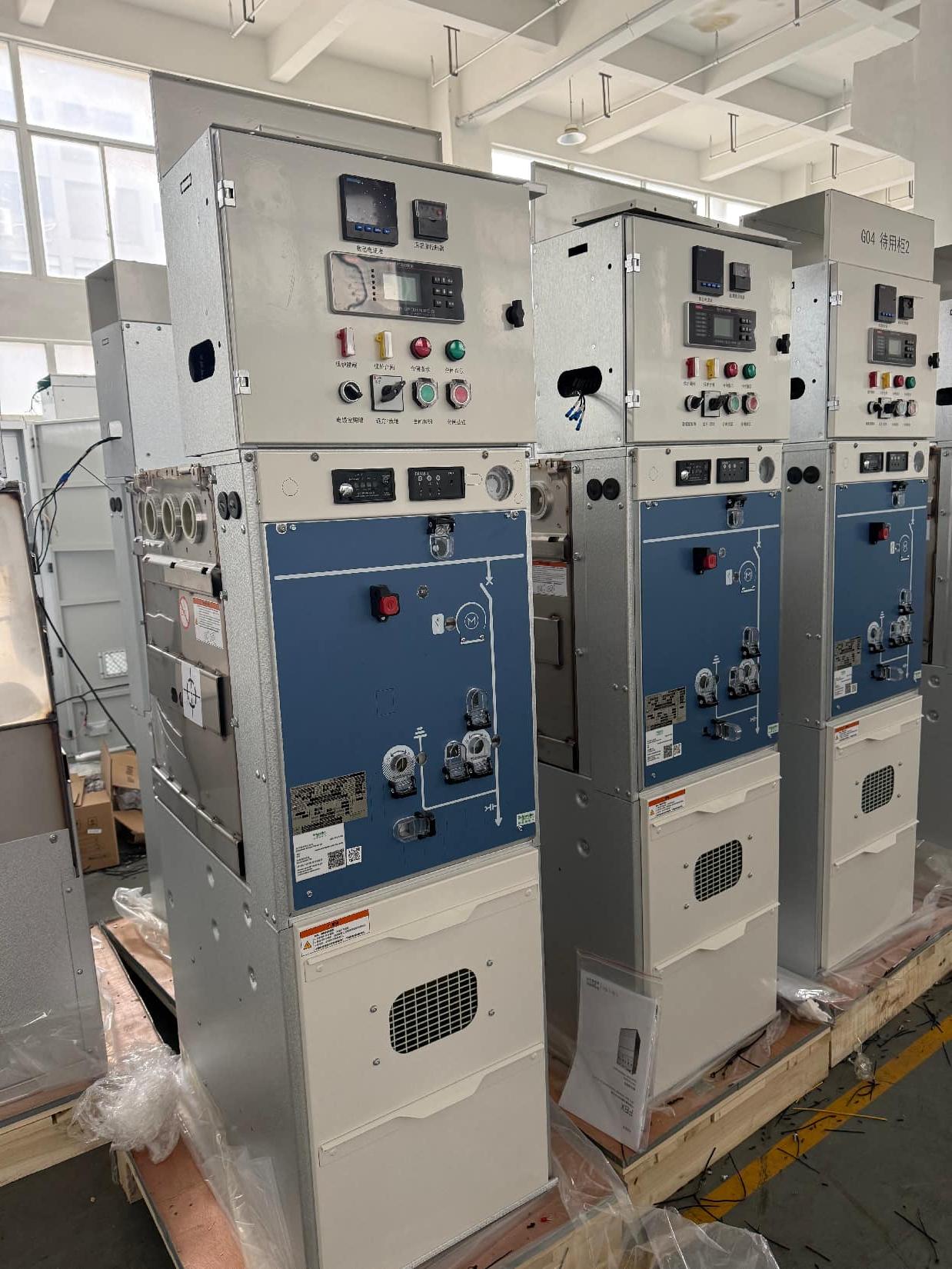
Busbar contact pressure rarely shows up on a thermal scan until it's already caused trouble. You can have identical torque specs, clean surfaces, and proper bolt sizes, yet one joint runs 20°C hotter than its neighbor. The difference often comes down to how the clamping force distributes across the mating faces—something few maintenance routines actually measure.
Over time, thermal cycling works against you. Copper and aluminum expand at different rates, bolts relax, and oxide layers creep into the interface. Even a slight loss of contact pressure pushes current through fewer contact points, raising local resistance and creating the kind of hotspot that accelerates further degradation. It's a feedback loop that starts silently.
The practical fix isn't just retorquing on a schedule. It's understanding that contact pressure is a dynamic variable, affected by plating condition, surface flatness, and even the sequence in which fasteners were tightened. Measuring voltage drop across each joint under load gives you a far better picture than an infrared camera ever will.
Vacuum Interrupter Wear Patterns and Their Impact on Switching Endurance
Vacuum interrupter wear patterns develop through repeated arcing and mechanical contact operations, each leaving distinct signatures on the contact surfaces. Microscopic pits, craters, and zones of localized melting form as the arc root migrates during current interruption, while material transfer between anode and cathode creates uneven protrusions and depressions. These surface irregularities are not merely cosmetic; they alter the electric field distribution and reduce the effective contact area, setting the stage for progressively higher contact resistance and localized overheating.
As wear accumulates, metal vapor and droplets condense on internal shields and ceramic walls, gradually forming conductive or semi-conductive films. This contamination narrows the insulation clearances and can trigger partial discharges or even restrikes after current zero, particularly under high di/dt conditions. Frequent short-circuit interruptions accelerate the formation of deep erosion channels and cracks, which may propagate under thermal and mechanical stress, eventually leading to contact welding or failure to interrupt.
The cumulative effect of these wear patterns directly dictates switching endurance. Each interruption consumes a fraction of the contact material, and the rate of consumption depends on arc energy, contact material composition, and the design of the arc control structure. Once the wear exceeds a critical threshold, the interrupter's ability to sustain dielectric recovery after arcing degrades sharply, resulting in premature failure or unreliable operation. Monitoring wear indicators such as contact gap reduction, increasing contact resistance, or abnormal arc voltage waveforms becomes essential for predicting remaining service life and avoiding unexpected outages.
Epoxy Insulation Curing Conditions That Decide Partial Discharge Levels
The relationship between epoxy insulation curing conditions and partial discharge (PD) levels is often underestimated in production. Small deviations in cure temperature or time shift the crosslink density, leaving micro-voids or residual internal stress that act as initiation sites for discharges. For instance, an under-cured epoxy may retain unreacted hardener pockets that lower local breakdown strength, while an over-cured system can embrittle and crack under thermal cycling, both of which raise PD magnitude well before catastrophic failure appears.
Practical experience shows that a stepped cure profile—rather than a single high-temperature soak—tends to produce lower and more stable PD readings. Raising the temperature too quickly traps volatiles or creates uneven gelation, particularly in thick sections or around embedded conductors. Conversely, a slow ramp followed by a moderate post-cure anneal allows the network to relax and reduces residual mechanical strain at electrode interfaces. Many manufacturers overlook the post-cure stage, yet it is often this phase that separates batches with PD below 10 pC from those exceeding 50 pC under identical test voltages.
Beyond the oven recipe, the surrounding environment during cure also influences discharge behavior. High humidity or contaminated mold surfaces introduce ionic species into the epoxy matrix, increasing conductivity and leading to surface or internal PD at lower electric fields. Vacuum-assisted curing or dry-air purging during gelation can remove dissolved gases and moisture, resulting in a denser, more homogeneous insulation. As a rule, monitoring the cure by dielectric response or glass transition temperature—rather than relying solely on time and temperature charts—gives a better prediction of the final PD level before the part ever reaches the test bench.
Auxiliary Circuit Routing Mistakes That Trigger Unplanned Breaker Trips
Routing auxiliary circuits too close to high-current power conductors is a common oversight that leads to nuisance tripping. When low-voltage control wiring runs parallel to feeder cables for long stretches, electromagnetic interference can induce enough voltage to falsely signal a fault. This often happens in crowded wireways where installers prioritize neat bundling over separation distances. The result is a breaker that opens without any actual overload or short circuit, leaving technicians scratching their heads.
Another frequent mistake is passing auxiliary circuit conductors through the same conduit as motor start or stop leads without proper shielding. Inrush currents during motor starting can couple transient spikes onto adjacent control lines. If those lines feed into a shunt trip or undervoltage release, the breaker may trip the instant a large load energizes. The fix usually requires rerouting the sensitive wiring into a dedicated metallic raceway and adding twisted-pair or shielded cable, but many facilities overlook this until repeated false trips force an investigation.
Poor grounding of auxiliary circuit shields or drain wires also contributes to unexpected breaker operation. A shield that is left floating at one end acts like an antenna, picking up noise from variable frequency drives or welding equipment nearby. When that noise reaches a trip unit's input terminals, it can exceed the pickup threshold momentarily. Properly bonding the shield at a single point and routing the circuit away from harmonic-rich sources are simple corrections that often stop the unplanned trips without replacing any breaker components.
Torque Audits and Thermal Imaging: Field Checks That Prevent Slow Failures
A torque audit isn't about chasing every fastener with a wrench. It targets the joints where thermal cycling, vibration, or soft metal creep gradually relax clamping force. On a motor control center, for instance, the lugs on a contactor can lose 15-20% of their original torque within a year of commissioning. That reduction isn't visible, but it raises contact resistance and starts generating heat long before a thermal overload trips. Checking a sample of critical connections with a calibrated torque wrench takes less than an hour and catches the loose ones while they're still tight enough to avoid damage.
Thermal imaging picks up where torque audits leave off. A handheld camera can sweep a live panel and reveal hot spots that point to loose terminations, overloaded phases, or failing breakers. The key is not just finding a warm spot, but comparing it to similar components under similar load. A 10-degree rise on one lug of a three-phase feeder is a warning sign; a 30-degree rise means schedule an outage soon. These images also give you a baseline, so next quarter's scan shows whether the problem is worsening or stable.
Neither method is complicated, which is exactly why slow failures hate them. A torque audit restores mechanical integrity before it becomes electrical heat. Thermal imaging catches the heat that torque misses, like internal contact wear or unbalanced loads. Together they form a field check routine that costs a few hours per quarter and prevents the kind of failures that never announce themselves until an entire production line goes dark.
FAQ
Its fully compartmentalized metal-clad layout keeps busbars, breakers, and cable compartments separated. This isolation limits damage during internal arcs and simplifies targeted maintenance, which helps utilities avoid prolonged outages.
Look beyond basic certifications. Examine their testing routine for partial discharge, mechanical endurance, and temperature rise under load. Ask for references from substations or industrial plants with similar operating conditions, and verify how they handle spare parts and after-sales support.
Vacuum interrupters extinguish arcs quickly inside a sealed bottle, minimizing contact wear and eliminating the need for oil or SF6 gas. In KYN28-12 panels, this translates to lower fire risk, reduced maintenance, and stable breaking performance over many operations.
Regular thermal scanning of busbar joints, checking the alignment of the earthing switch, and verifying the interlock mechanisms are non-negotiable. Clean insulation surfaces and test the vacuum degree of the breaker every few years. Skipping these steps invites unexpected failures.
It excels in compact substations, data centers, and mining operations where floor space is limited and protection against harsh environments matters. The metal-clad enclosure offers better arc containment and higher personnel safety than open air-insulated units.
The mechanical interlocks enforce a strict sequence: the breaker must be open before the truck can move, and the earthing switch cannot close while the breaker is in service position. This prevents dangerous live operations and accidental grounding of energized circuits.
Proper clearance and creepage distances, along with high-quality epoxy resin insulators, reduce the chance of surface tracking and flashover in humid or dusty conditions. A manufacturer that tests insulation under simulated environmental stress gives you a more dependable unit.
Conclusion
Achieving dependable service from KYN28-12 medium voltage switchgear demands attention to a handful of interacting details that rarely appear on standard datasheets. Panel geometry matters because compartments designed to channel and cool expanding gases during an arc event keep pressure from turning into a personnel hazard. At the same time, busbar joint pressure is a silent variable: even a slight relaxation of clamping force raises contact resistance, and repeated load cycling can create thermal hotspots that degrade insulation long before a direct fault appears. Vacuum interrupters demand similar scrutiny, as contact wear patterns differ between load-breaking and fault-interruption duties; tracking erosion across operations gives a realistic picture of switching endurance rather than relying on a generic cycle count.
Manufacturing consistency in epoxy insulation is another quiet determinant of partial discharge levels, since cure temperature and time directly influence void formation and surface resistivity. Field practices then keep the equipment honest: routing auxiliary circuits away from high-energy conductors prevents induced voltages that trip breakers without command, while periodic torque audits and thermal imaging catch loosened connections and uneven heating early. Together these factors turn a well-built switchgear line into a long-term asset, because reliability comes less from any single component than from the disciplined control of pressure, heat, wear, and dielectric stress across the entire panel.
Contact Us
Contact Person: Hellen
Email: [email protected]
Tel/WhatsApp: 86-13634205622
Website: https://www.voltcabinet.com